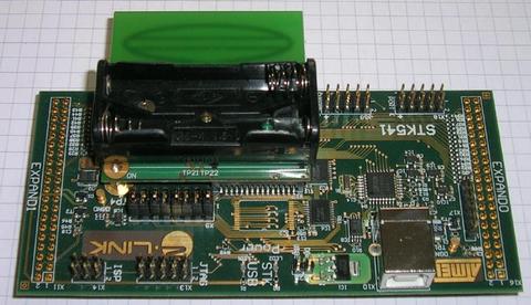
The Packet Sniffer Kit STK541 is a carrier board, which fits on top of a STK500 and is used for the radio controller board family. The transceiver wiring fits the common RCBs. The wiring of the radio and the ATmega is shown below:
     AVR      RF230
     ---      -----
     PB4  -->  SLPTR
     P??  <--  MCLK
     PD4  <--  IRQ (ICP1)
     PB5  -->  RSTN
     PB0  -->  SS
     PB2  -->  MOSI
     PB3  <--  MISO
     PB1  -->  SCK
    The STK541 has no LEDS and Keys, so we define the ressources
    from the  RCB230 here.
    KEY: PE5
    LEDS: PE2:PE4
DBG: PD0 - connector X20:2 (ground X20:1)
Fuses/Locks:
     LF: 0xe2 - 8MHz internal RC Osc.
     HF: 0x11 - without boot loader
     HF: 0x10 - with boot loader
     EF: 0xff
     LOCK: 0xef - protection of boot section
Bootloader:
    Start at byte=0x1e000, address=0xf000, size = 4096 instructions/ 8192 bytes
Atmel STK541 and Radio Controller Board
Definition in file board_stk541.h.
Go to the source code of this file.
Defines | |
| #define | BOARD_NAME BOARD_NAME_STK541 |
| #define | DBG_DDR DDRD |
| #define | DBG_PIN (1<<PD0) |
| #define | DBG_PORT PORTD |
| #define | DDR_KEY DDRE |
| #define | DEFAULT_SPI_RATE (SPI_RATE_1_2) |
| #define | FT245_DDR DDRE |
| #define | FT245_INIT() |
| #define | FT245_PIN PINE |
| #define | FT245_RX_DATA() ((FT245_PIN & FT245_RXF)) |
| #define | FT245_RXF _BV(7) |
| #define | FT245_TX_DATA() ((FT245_PIN & FT245_TXE)) |
| #define | FT245_TXE _BV(6) |
| #define | HIF_IO_ENABLE XRAM_ENABLE |
| #define | HIF_NO_DATA (0x0100) |
| #define | HIF_TYPE (HIF_FT245) |
| #define | HWTIMER_REG (TCNT1) |
| #define | HWTIMER_TICK ((1.0*HWTMR_PRESCALE)/F_CPU) |
| #define | HWTIMER_TICK_NB (0xFFFFUL+1) |
| #define | HWTMR_PRESCALE (1) |
| #define | INVERSE_KEYS (1) |
| #define | LED_DDR DDRE |
| #define | LED_MASK (0x1c) |
| #define | LED_NUMBER (3) |
| #define | LED_PORT PORTE |
| #define | LED_SHIFT (2) |
| #define | LEDS_INVERSE (1) |
| #define | MASK_KEY (0x20) |
| #define | MAX_FRAME_SIZE (127) |
| #define | PIN_KEY PINE |
| #define | PORT_KEY PORTE |
| #define | PULLUP_KEYS (1) |
| #define | RX_HAS_DATA (0) |
| #define | RX_HAS_NO_DATA (FT245_RXF) |
| #define | SHIFT_KEY (5) |
| #define | TIMER_INIT() |
| #define | TIMER_IRQ_vect TIMER1_OVF_vect |
| #define | TIMER_POOL_SIZE (4) |
| #define | TIMER_TICK (HWTIMER_TICK_NB * HWTIMER_TICK) |
| #define | TUNED_OSCCAL (0xbf) |
| #define | TX_IS_BLOCKED (FT245_TXE) |
| #define | TX_IS_READY (0) |
| #define | USB_FIFO_AD 0xF000 |
| #define | XRAM_ENABLE() XMCRA |= (1 << SRE); XMCRB = (1 << XMBK) |
| #define BOARD_NAME BOARD_NAME_STK541 |
ID String for this hardware
Definition at line 109 of file board_stk541.h.
| #define FT245_INIT | ( | ) |
Value:
do { \
           FT245_DDR &= ~(FT245_TXE|FT245_RXF);\
        } while(0)
Definition at line 154 of file board_stk541.h.
| #define MAX_FRAME_SIZE (127) |
maximum allowed frame size
Definition at line 113 of file board_stk541.h.
| #define TIMER_INIT | ( | ) |
Value:
do{ \
        TCCR1B |= (_BV(CS10));\
        TIMSK1 |= _BV(TOIE1); \
    }while(0)
Timer is clocked at F_CPU, and TIMER_IRQ_vect is called every 65535 ticks.
Definition at line 184 of file board_stk541.h.
| #define TIMER_IRQ_vect TIMER1_OVF_vect |
Vector for Timer IRQ routine
Definition at line 173 of file board_stk541.h.
 1.5.5
1.5.5